Contents |
Preface
Creating new 32bpp graphics for OTTD is easier than you might think. Basically, only 2 steps are needed:
- Create a png file (with the right name and put it the right directory)
- Pngcodec the png file (sounds complicated, but it just adds some data to the png file, so OTTD can show it correctly ingame)
For this tutorial, it is recommended that you have the following software installed on your system:
- Blender (3D model creator and renderer)
- The GIMP (2D image manipulation program), although Photoshop or comparable programs might work just as well
- pngcodec (adds meta data to png files)
All these programs are available for most major OS', so it doesn't matter whether you use Linux, Windows, MacOS or similar operating systems, although this tutorial will focus on how things are done in Windows.
For the advanced tutorials, you will also need:
- The template .blend file. It is based on Aracirion's official lighting setup .blend file and includes a slightly revised version of brupje's blender_render.py python script that automates rendering in Blender.
- brupje's blender_convert tool that automates pngcodec'ing
- grfcodec (converts .grf files into .pcx files and vice versa)
Step 1: Getting to know the .grf files
While OpenTTD does not currently support extra zoom sprites, there are nearly 7000 sprites in the game that have to be replaced to make it fully 32bpp, of which almost 4800 are in the trg1r.grf (TTD) or ogfx1_base (OpenGFX) file, so plenty of artwork will have to be created before completely new sprites might be included. Each of these sprites has a unique ID that can be obtained by decoding the corresponding .grf file using grfcodec.
For many of these you will prefer the nice, 3D-like look that you get from images rendered in blender, but for some, GIMP will suffice. Let's make a new mouse pointer. It has ID#0 in the trg1r.grf, being the first sprite (the second one has ID#1 and so on). Make a nice pointer (or just copy the example cursor) in GIMP, and save it as a .png file to the following folder:
your drive:\your ottdfolder\data\sprites\name of grf file\ID of sprite.png
For example:
d:\ottd\data\sprites\ogfx1_base\0.png
Your sprite is now where it belongs. But OTTD needs information on how to display it correctly. This is done by adding offsets to the png file. Offsets determine how far the actual graphic will be shifted from the origin of the sprite in x (horizontal) and y (vertical) direction. For the mouse pointer, the origin is the top left corner. Unfortunately, it's not that simple for many other sprites. To learn more about offsets, see the NewGRF wiki (scroll down) - or keep on reading. The offsets can be included in the png file as meta data. You need the pngcodec.exe for that. Just place it in the same folder that contains your sprite. Now you execute the Windows command prompt (start->run->cmd.exe). Go to the ogfx1_base folder and write the offsets:
d:\ottd\data\sprites\ogfx1_base>pngcodec a 0.png x_offs=-0 y_offs=-0
The offsets are zero because the origin of the sprite defines the tip of the pointer. In this example, the top left corner of the png file also contains the tip of the pointer, so the graphic doesn't need to be shifted. Start OpenTTD to see your creation ingame.
Suppose we turn the cursor by 180 degrees. Now the tip faces the bottom right corner. This confuses OpenTTD, as it still wants to assign the top left corner to the tip. Our sprite is 60x60 pixels (that's why it looks so big; the original sprite is only 24x24), so if we move it left by 60 pixels (x_offs=-60) and up by 60 pixels (y_offs=-60), everything should align properly again. If yours has different dimensions, modify the offsets accordingly. Bear in mind that negative offset values move the sprite left/up, while positive values move it right/down. Offsets are usually negative.
d:\ottd\data\sprites\ogfx1_base>pngcodec a 0.png x_offs=-60 y_offs=-60
A cursor with a twist!
Step 2: A simple house in Blender
While you could replace all the sprites with only GIMP and pngcodec, using Blender to create 3D models will give you graphics that may have a lot more visual appeal. Furthermore, it makes sure that the lighting and the casting of shadows will be consistent in the game, even when many users have contributed graphics. To follow this tutorial you should be able to navigate and place and edit simple objects in Blender. Blender has a rather steep learning curve, and that is what puts many people off. It shouldn't put you off, though. The results once you've mastered it will be very rewarding. Please allow yourself a few hours to get accustomed with the software and start experimenting. Excellent tutorials can be found in Wikibooks and on the official Blender page.
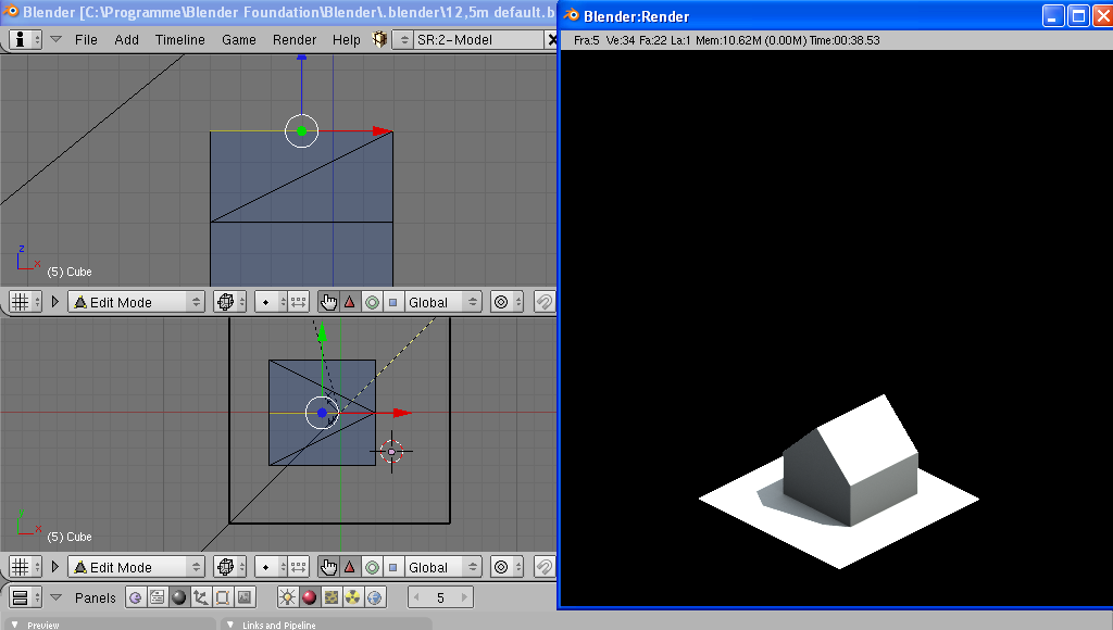
Still here? Back after a few hours? Up to the task? Let's start. First get the right .blend file. This was created by Aracirion and contains the current official lighting setup. What you're looking at when you open it is a single tile that is surrounded by a black border. Hit F12 to see it rendered. A tile is 12.5mx12.5m in the game. Please note that every tile is divided by the Blender grid into 12.5x12.5 units in the 3D view. To put it differently, the distance between two grid lines is 1m. Make a simple house, keeping the scale in mind.
To make it look less bland, colour the walls and roof by assigning different materials to them. You might even add some textures. You can find nice ones on (http://www.cgtextures.com/).
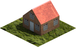
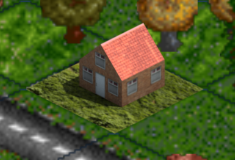
When you are happy with your results, hit F12 one last time to render your creation. OTTD doesn't have a rotatable map yet, so one camera angle will suffice. Let's replace the old cottage
with the tutorial house. The old cottage has ID#1496, so save the png to your trg1r folder as 1496_z0.png. The _z0 suffix tells OTTD that this is a graphic for the closest zoom level. The second level gets a _z1 suffix, the third (normal) zoom level a _z2 suffix. However, _z0 are automatically scaled when you zoom out, so all we need at the moment is the _z0 file. You should get a .png image that is 512x512 pixels. This contains a lot of empty space, however, so lets cut it down to size in GIMP (Image->Autocrop image). You should end up with an image that is 256 pixels wide. The height would be 128px for a flat tile, but with your house on it, it will be higher. Save your image over with the cropped version. Now the offsets have to be assigned. For buildings, the origin of the sprite is the top corner of the bounding box. Yes, OTTD has bounding boxes (like in those 3D action games... well, almost) that indicate the dimensions of the buildings. To see them ingame, hit Crtl+B while playing. Don't do this while zoomed in though, or your game will crash. For most buildings, the bounding box covers the whole tile, 256x128 pixels (or 64X32 pixels in standard zoom). The top corner of the bounding box is in the middle of the horizontal axis of your sprite, so the x_offs should be half of your .png file's width. That would be -128 in theory. However, counting the offset starts at 0 not 1 (and ends at 63, not 64) in standard zoom, so multiplying the difference by 4 (for z0 zoom) leads to an x_off value of -124. If that is too confusing for you, just remember to divide the width of you png file by 2 and subtract 4. That's your x_offs (don't forget it's a negative value). On to the y_offs value: if your tile were completely flat, it would be -0. At least in theory. Counting, however, starts at 0 in standard zoom, so your offset should be -4 in z0 zoom. Unfortunately, your tile isn't flat. There's a house on it that protrudes from the plane and makes the png file higher. To calculate the offset, you could find the top corner of the lawn, determine how far your sprite is extended by the house and add that value to your y_offs. Problem is, you can't see the top corner - the house is in the way. So it's a bit more confusing: measure the complete height of the sprite and subtract 127 from it to get the y_offs (it works!). The example house is 161 pixels high (yours will be different), so the y_offs is: 161-127=34 (offsets are usually negative, so it's -34)
Now you can write the offsets:
d:\ottd\data\sprites\trg1r>pngcodec a 1496_z0.png x_offs=-124 y_offs=-34
Now start OTTD to see your creation in game!
But wait, there's more to it!
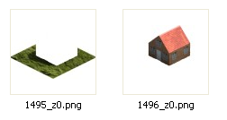
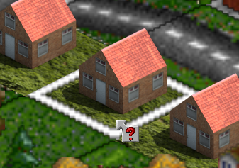
To put the building and the ground tile (the lawn) in a single sprite causes a few glitches. For example, the selector (that white rectangle that appears when you use the query tool) won't show on that tile. This is caused by the order the sprites are displayed in. For this reason, single tile buildings are normally split up in two sprites: The ground and the building. If you want to avoid these glitches, you have to separate the ground from the building. For the old cottage, the ground sprite ID is 1495. Use GIMP (or a similar application) to divide your sprite in two files, 1495_z0.png and 1496_z0.png. Leave the height and width the same as in your original file, with the building and ground correctly arranged. That makes setting the offsets easier.
Now you have to set the offsets for both files again (Important lesson here: the meta data gets overwritten when you edit the file!) Just use the offsets you determined earlier. That's it, glitches fixed!
The lawn texture used in this example doesn't look very consistent with the existing game artwork (yours may be better). That's why there has been an effort to collect nice and fitting textures here on the wiki. There's also a .blend file with standardised objects (official_materials.blend) found there that contains water, metal, pavement and grass, so it's a good start to have a look there first before you start a more ambitious project. Feel free to add materials and textures you designed yourself.
Step 3: A simple road vehicle in Blender
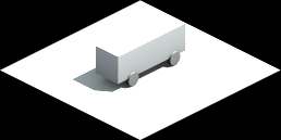
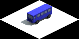
Now that you have the buildings figured out, let's move on to the transportation. We're going to create a simple road vehicle. Load the .blend file with the default lighting and draw a box with some wheels on it. Remember that all road vehicles in OTTD are half a tile (that's 6.25 meters or 6.25 blender units) long, so let's make it the same length (if it's much longer it will cause glitches).
Now that looks more like a freight wagon, if anything. Add some texture to make it look more bus-like. For the tutorial, put as much or as little effort into that as you feel like. It is important, however, that you are able to distinguish the front and back and the left and right side of the bus from each other, otherwise you will get confused when you apply the offsets.
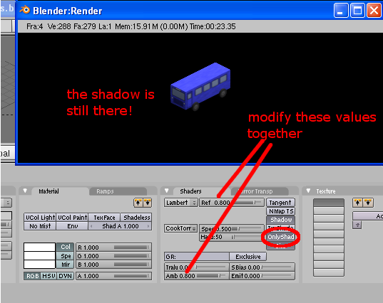
It has been agreed upon that the materials' shader values for reflectivity and ambient colour should be modified together. Setting both values to 0.8 is a good start. If you set these values too low, your model will look quite dark in the render. Hit F12 to examine your results.
Finally, you don't want the white ground tile to be rendered, or your bus will carry around a white rectangle when it moves ingame. But you still need to retain the shadow the bus casts on that tile, or your final result will look flat and cartoony. So set the Shader for the ground material (and only for the ground material!) to "OnlyShad". If you haven't done so yet, move your vehicle to the centre of the tile (the origin of the axes) and make sure the wheels are on the ground. No hover buses here! Now your model is ready for rendering. You need a total of 8 renders per zoom level, corresponding to 8 angles. Each angle differs from the previous and next by 45 degrees. With these renders you can replace the 8 sprites per bus in the trg1r.grf. Let's replace the Foster MkII Superbus. It has sprite IDs #3476 to #3483.
Manual rendering
This can be slightly tedious, but is similar to what you did for the house. Try it if you have problems with the automated approach described below, or if you are into DIY... You need to render 8 angles. After each render, you save the render image (F3) as ID#_z0.png (to yourottdfolder\data\sprites\trg1r\), rotate the model clockwise by exactly 45 degrees (keeping the middle of the bus on the origin of the axes and the wheels on the ground), and render again. You should end up with 8 files, named 3476_z0.png to 3483_z0.png. Please note that your first render most likely won't correspond to the sprite #3476. If the view is the same as in the example image (bus facing sw), you'll start with 3481_z0.png, then 3482_z0.png and 3483(...), then 3476, 3477 and so on to 3480. Always remember to check your sprite angle to the one in the trg1r.grf. Now you need to open each file in GIMP and autocrop it. This will give you much smaller files, with the bus roughly in the middle (your mileage may vary for Photoshop or similar programs. If all else fails, use GIMP, it's free.). That's a good thing, because the origin for vehicle bounding boxes (see above) is the middle of the sprite. So the x_offs and y_offs are roughly half of the sprite's width and height. Make a table with the dimensions of each sprite and the half of each value. If you end up with decimal places, round to the next integer (there are no half-pixels...!). Remember that offsets are usually negative.
| Sprite ID | Viewing angle | Width | Height | x_offs | y_offs |
| 3476 | N | 131 | 92 | -66 | -46 |
| 3477 | NE | 134 | 85 | -67 | -43 |
| 3478 | E | 145 | 70 | -73 | -35 |
| 3479 | SE | 134 | 85 | -67 | -43 |
| 3480 | S | 128 | 90 | -64 | -45 |
| 3481 | SW | 135 | 84 | -68 | -42 |
| 3482 | W | 146 | 70 | -73 | -35 |
| 3483 | NW | 136 | 85 | -68 | -43 |
Now use pngcodec as described above to add the x_offs and y_offs values to each sprite
d:\ottd\data\sprites\trg1r>pngcodec a 3476_z0.png x_offs=-66 y_offs=-46

d:\ottd\data\sprites\trg1r>pngcodec a 3477_z0.png x_offs=-67 y_offs=-43
etc.
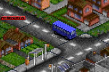
Start OTTD to see your creation in game (don't forget to set the year to 2020 or some similar value, or your bus may not yet be available).
Excellent. Fast and reliable public transport for the world of tomorrow!
Automated rendering
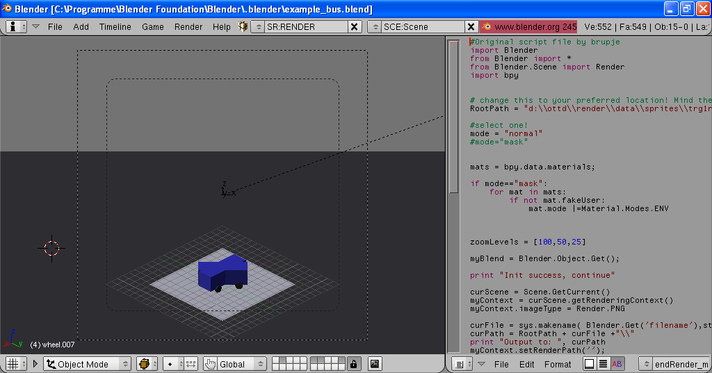
Rendering the viewing angles by hand might be feasible for 8 sprites, but will get more and more tedious if you decide to render the _z1 and _z2 zoom levels as well. And the mask files for variable company colours (we'll get to that later). For a standard vehicle, you will usually end up with 48 files. That's where you might want to resort to automated rendering and coding. You need the blender_render.py python script and the blender_convert program for that, respectively. Both were developed by brupje. The python script is already included in the template .blend file, while you can find a link to the blender_convert.exe in the preface. For this script to work properly, you need to observe the following:
- The model you want to render has to be in one of the layers 6 to 9, preferably in layer 6.
- It will be rendered in 4 different angles, all rotated by 90 degrees.
- Layer 10 is reserved for the lighting sources and the tile surroundings. It is always active.
- Layer 2 is also always active, in the unlikely case that you want an object to appear the same on each layer.
- All objects in layer 1, 3, 4 and 5 are ignored.
Place your model in layer 6. As you want 8 different angles, you have to duplicate it and move the copy to layer 7. Rotate it clockwise by 45 degrees. Modify the settings in the script file so that the rendered pictures will be saved to the directory of your choice. Select normal mode, access to layers 6 and 7 and rendering of _z0 sprites only. Place the text input cursor (the red bar) in the first line of the script, then hit [Alt+P] while your mouse cursor is in the text window to activate the script. Lean back, get a coffee or water the pot plants. If everything works fine, it will render 8 images. They will be placed in a subfolder with the name of the .blend file in the location you've specified.
We're not going to be bothered with creating proper company colours masks yet, but blender_convert.exe, the pngcodec'ing tool, requires at least some "dummy" mask files to work. So let's render these too, by activating the mask mode in the python script and starting it again (remember to reset the cursor!). It should quickly render 8 empty mask files (If the mask files are not empty, you either have objects without a material on your layer, or you have materials with fakeusers. Don't bother for now, we won't use these mask files anyway). If you haven't done so yet, download blender_convert, and extract the contents of the zip file to a destination of your choice. I chose d:\ottd\bc\ A short caveat: the program is in a usable, but early stage of development. So don't expect a gui. Do, however, expect it to crash if it encounters a problem. But if you feed it the right data, it works like a charm. Create an empty .txt file called rename.txt in the folder that contains your 16 rendered files. Don't write anything into it yet. The program needs the file, or it will crash. Later, we'll put useful data into it. Run blender_convert once from the command prompt.
yourbcfolder>blender_convert locationofsprites\
e.g.
d:\ottd\bc>blender_convert d:\ottd\data\sprites\trg1r\example_bus\
You'll find a new subfolder called "output" in your folder. blender_convert has autocropped all images for you. Now take a note of the image dimensions again, as described above for the manual process. You can now delete the output folder. We're going to start bc again with a "proper" rename.txt. Divide all dimensions by 2 and take the negative values. Find out which file corresponds to which sprite ID. Better draw a table again for your personal reference. Now open the rename.txt. The information for codecing is entered as follows:
filename_of_source <-no .png suffix!
sprite_id
x_offs
y_offs
e.g.
example_bus_2_7
3476
-66
-46
example_bus_2_6
3477
-67
-43
example_bus_1_7
3478
-73
-35
.... <- and so on for each sprite angle.
Finish each line by hitting enter. Don't use empty lines, tabs or unnecessary blanks. Bc doesn't like those at all! You should end up with a rename.txt that is (8x4=)32 lines long. Now run bc again as described above. This time, it will autocrop, pngcodec and rename all files automatically. Good times! (If it crashes or gives wrong filenames or offsets you probably have a typo in your rename.txt) Get all 8 bus sprites from the output folder (you can delete the mask files in this case. They're just blanks, you haven't created proper ones yet) and copy them to your trg1r folder. Now start OTTD to see your creation in game. All right!
By the way, in case you've wondered why the automated approach is more time consuming than the manual approach: it will get much easier when you get used to the way the tools work, by which time it will really save you a lot of time. It's also much easier to apply company colours that way. Have I mentioned the mask files yet...?
Step 4: Applying Company Colours
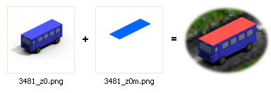
If you've followed the preceding step, you may have noticed that your bus looks the same, no matter what company colour you choose. That's fine if you want it to have the prototypical livery, for example, but gameplay-wise it is preferred to have at least part of your model show the respective company colour - or it will be hell to find your buses in a big city where several companies operate! Company colours are applied by making an additional file for each sprite that has the same dimensions as the original one. In this file, all areas that are to show company colours are marked in blue, while the rest is transparent. This is known as a mask file. Mask files have the same file name as the parent file, but with an "m" added before the .png suffix. So the mask file for 3476_z0.png would be 3476_z0m.png. Important note: mask files do not have to be pngcodec'ed. They get their offsets information from the parent sprite.
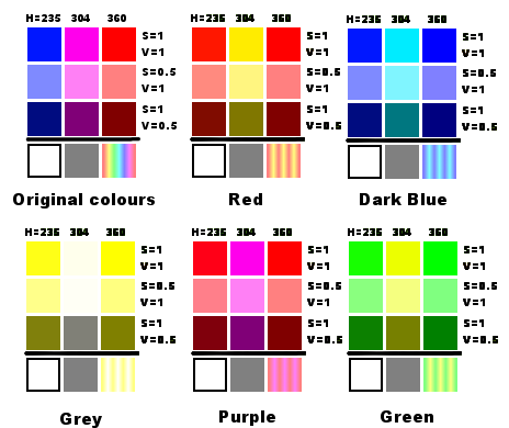
Mask files add company colour to the sprites depending on the HSV values of the sprite's regular colour in the affected areas. That's Hue (the colour), Saturation (the "colourfulness") and Value (the lightness/darkness). There are two pincipal company colours (although that shouldn't be confused with the 2nd company colour) in each colour scheme, that are alternated for every 60 degrees of hue. Confused? It simply means that the primary colours red, green and blue (RGB model, remember?) get the first colour, while the "mixed" colours yellow, cyan and magenta get the second colour. A colour in between these causes mixing of the first and second. Please note that while GIMP uses the more logical 360 degrees scheme for hue values, Blender has values between 0 and 1. Fortunately, these values can easily be converted directly.
It's easier for the S and V: The saturation and the value of the original colours directly influence the saturation and value of the company colours. A very low saturation value will lead to almost no company colour being applied, so shades of grey, black and white will stay colourless. It is done that way so that minor details, like shadows, contours and textures are not lost. Mask files have to be 8 bit. That's a limitation imposed by the way OTTD handles company colours. The result ingame will be 32 bit, however, so don't worry that it may be a step backwards! Let's make a mask file for our example bus. If your bus has a very desaturated colour, like white, grey or black, you might want to change that colour beforehand, or the outcome might be unsatisfactory.
Manual generation of mask files
Use GIMP (or a different image manipulation program) to open the parent .png file (for example, 3481_z0.png). Add a second layer. In this layer, colour all the areas that you want company colour to be applied to. Disable (hide) the parent layer, so that only the mask is visible. Save the result as the corresponding mask file (3481_z0m.png). Now reload the mask file. This way you will get rid of the parent layer (You can also simply delete it without reloading). Convert the image to 8 bit by selecting Image->mode->indexed. Gimp will prompt you to select a palette. Select "Use custom palette" and make sure that "remove unused colours from final palette" is NOT selected. You need to retain at least 196 colours in the palette. I normally choose the "Web" palette. If other palettes don't work for you, try that one. Open the colour map (Dialogs->colormap). Choose a colour with an index# between 196 and 203 to colour your mask file. Reportedly, the actual colour doesn't matter, as long as its in that range. Masks are usually drawn in blue, so if there's a nice blue in that range, choose it (I won't vouch for red or yellow masks to work just as well...) and dye the coloured areas in your mask a nice blue. Save the file again. Now all you have to do is to repeat this for all remaining sprites, start OTTD and check the results. Well done!
Automated generation of mask files
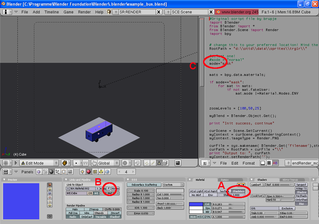
This is blender_render's time to shine. If you've followed step3, you will have noticed that we skipped over the issue of mask files quite quickly. Now we're going to make "proper" mask files. Important for the render script is that you have a "fakeuser" flag set for every material that you want to show up as company coloured later on. That is the small "F" button in the Shaders->materials->links and pipeline section. Click it and watch the number of data users go up by one. If it instead goes down by one, that material already had the "fakeuser" flag set. Also, you can determine whether a material has a fakeuser in the materials selection dialog. If it has an F in front of the material's name, it has one. For this tutorial, only colour the roof. Assign a fakeuser to the roof's material. If it shares its material with some other parts of the bus, you have to assign it a separate material. Set the material to Shadeless, to avoid colour distortion issues and speed up the rendering process. You may also want to switch off all textures that are assigned to the material. It won't need them, anyway. Make sure you edit the bus's materials on both layers (6 and 7). Select the mask mode in the blender_render.py by commenting out the normal mode and "commenting in" the mask mode. Place the text cursor in the first line of the script, hit [Alt+P] to activate it and let the script do the work for you. Now just start blender_convert as described above, using your old rename.txt. Make sure the unprocessed 3D renders from step 3 and the mask files from this step are in the same folder. It should write new output sprites, all with the corresponding mask files, neatly converted to 8bpp (indexed colours). Copy them to your trg1r folder, start OTTD and you're done!
But wait, there's more to it!
If you experience glitches, like the original colour of the sprite showing, especially on the edges and the outline of the sprite, you have to tweak your mask files. Often, moving the masks up by one pixel in GIMP does the trick (just save over the old file - mask files don't have to be pngcodec'ed - but leave the image in indexed (8bpp) mode). If that still doesn't work, try expanding the masks by one pixel in each direction. If the outcome is still unsatisfactorily, you have to edit the masks pixel by pixel, taking a note of where the original colour shows, then expanding the mask in that direction - but that is rarely necessary. If your sprite looks fine in z0 zoom, but you see some of the sprite's original colour on more zoomed out levels, you might also try shifting and/or expanding the mask. If that doesn't work, you have to render the z1 and z2 sprites and the corresponding mask files, so the misaligned zoomed out version will be overwritten by the pre-rendered version of the sprite.
Step 5: Wrapping things up
If you followed the preceding two steps, you should have ended up with 16 files (8 angles + 8 mask files) for the bus in your trg1r folder (48 if you also rendered z1 and z2 zoom). That's fine for test play, tweaking offset values and such, but if you want to release your creation for the general public, you will find most users can't be bothered to download 16 separate files. So you have to pack them into one single archive. Conveniently, OTTD already has the built-in ability to read archives, so users don't need to unpack the files on their system. Inconveniently, at least for Windows users, it can only read .tar files, an archive system more common on Unix/Linux. You need to get a file archiver that supports writing .tar. WinZip and WinRAR are not suitable. I recommend PeaZip. If you want more to choose from, check this comparison chart. The .tar files normally go in the data folder of ottd, while your sprite files are in data\sprites\trg1r\. You have to mimic that folder structure in your .tar file. So the internal structure of your archive file would be
sprites\trg1r\ <-and all your sprites go into that folder
If you want to, you can add a .txt file in the main folder of your archive. OTTD will ignore it, but you can use it to describe the contents of the archive, give installation instructions, historical information about the structure, vehicle, tree (??) you made, rant about politics (please don't!) or say hi to all your friends. However, keep this to a moderate length (think of the bandwidth!). What's even more important, you can include a license in that .txt file. Normally, OTTD users take copyright issues very seriously and people that rip your files for content will get quite a talking to on the forums. But if you'd like (or just don't mind) people to build on from your work to create more graphics, please include a license, such as the Creative Commons or GFDL, stating that it's OK to do so. You might also want to release the .blend file for others to work on - but separate from the .tar, please. Post your work on the forums, and you're done. Thanks for contributing to the world of 32bpp OpenTTD!


